To Create a Wiring Diagram Symbol (Terminal)
Wiring diagram
symbols can be made to represent a single terminal or a group of terminals. The
following example shows how to create a symbol that represents a group of six
terminals. In this example, you will import connection points from the 6BLOCK
family. This family is not provided with the software, but can easily be
created in the
Catalog Manager. Use the following entries:

After you have created the family, use the following steps to create the wiring diagram symbol:
- Select The Create Symbol option from the Manage ribbon to display the Symbol Creation Wizard.
- In this example, you will create a symbol from scratch. Select New Symbol (from Scratch), then press Next.
- In Step 2 of the Symbol Creation Wizard, enable the Wiring Diagram option within the Symbol Type group-box to define the symbol type, then press Next.
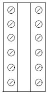
- In Step 3 of the Symbol Creation Wizard, you will import connection points from a similar symbol or family to save time. First, however, you will draw the graphics of the symbol using graphical drawing functions (not wires). Make the symbol approximately 3.5 inches (90 mm) tall.
- Once the graphics are drawn, enable the Import Connection Points From a Family option, then press Select Family to display the Device Family dialog.
- Select the family 6BLOCK, then press OK.
- Press Next in the Symbol Creation Wizard.
- In Step 4 of the Symbol Creation Wizard, you can enter information in the Tag Mnemonic field to indicate a default device tag (this is not required). The ID will be taken from the schematic symbol the wiring diagram symbol is representing.
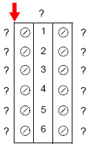
- Enter a question mark ( ?) as a default value in the Tag Mnemonic field. If desired, you can make text settings for the device ID in the Default Text Style field.
- Press Place, then click on the desired position for the device ID in the drawing. This text will take the terminal strip ID when the symbol is placed.
- The terminal numbers from the imported family are also listed in Step 4. Place these terminal number attributes in the drawing by first selecting (highlighting) a terminal and then pressing Place. You can place them one at a time or you can use the Select All button to place them one after another in the drawing.
- After a terminal number is placed, it is marked with an X in the Symbol Creation Wizard in the left-most column.
- Press Next to continue.
- In Step 5 of the SymbolCreation Wizard, you will place connection points on the symbol to set where the connection information will be displayed.
- The imported connection points from the family that you selected in Step 3 are displayed. The Visible Text entry (?) is a default value for the connection point text. The software will replace the visible text with the connection expression defined in the Wiring Diagram Settings dialog. The Hidden Text entries are the connection point designations that were defined in the family. If you had not imported connection points from a family or symbol, you could make an entry in the Number of Connection Points field to create the connection points. Because you imported connection points for this symbol from an existing family, there are also entries in the Role column for each connection point indicating the terminal number that the connection applies to. The terminal symbols have multiple connection points (designated I, E, J in this example). You will only place the I and E connection points in the wiring diagram symbol to represent the internal and external sides of the terminals.
- Make the desired text settings before placing the connection points. Use Middle Right text alignment for connections on the left side of the symbol. Use Middle Left text alignment for connections on the right side of the symbol.
- Select a connection point and then press Place. You will be prompted on the command line to select the connection point position and then the connection point text position. The placement of the connection points is not critical, but they should be on the same side of the symbol as the corresponding connection point text.
- After a connection point is placed, it is marked with an X in the Symbol Creation Wizard in the left-most column.
- Select Next to continue.
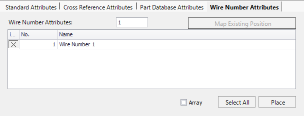
- In Step 6 of the Symbol Creation Wizard, you can specify symbol attributes. Click on the Wire Attributes tab and add the Wire Attribute for each terminal defined for the Wiring Diagram symbol in Step 11. This lets you control where the wire number for that terminal is displayed. For example, you may want to display the wire number in the center of the terminal with the From-To connections on either side of it.
- Press Next to continue.
- In Step 7 of the Symbol Creation Wizard, select the insertion point for the symbol by pressing Pick Point within the Insertion Point group-box, then click on the upper left corner of the symbol. A red arrow marks the selected point.
- Select Next to continue.
- In Step 8 of the Symbol Creation Wizard, you will name and save the symbol. Type W-EXTB6 in the Symbol Name field, then enter a description of the symbol in the Description field. Use the Save in field to select the catalog in which to save the symbol.
- Press Finish. Wiring Diagrams Overview